
Welcome! In this tutorial we’ll take a look at Routing Information Protocol (RIP). This is one of the oldest distance vector routing protocols, invented in the 1980s. Two versions of the protocol were developed:
RIP version 1 -supports only classful routing and doesn’t send subnet masks in routing updates.Uses broadcasts for updates.
RIP version 2– supports classless routing and sends subnet masks in routing updates. This version uses the multicast address of 224.0.0.9 to send routing updates.
There is also a version of RIP developed for IPv6 networks called RIPng.
RIP has a default administrative distance of 120. It uses the hop count (the number of routers between the source and destination network) as the metric. The hop count limit is 15. Any route with a higher hop count will be marked as unreachable.
Downsides of RIP:
- RIP sends the entire routing table every 30 seconds, which can consume a lot of network bandwidth.
- It lacks some more advanced of features of the newer routing protocols like OSPF or EIGRP and is not widely used in modern networks. For example, RIP doesn’t support route summarization.
Configuring RIP in Packet Tracer
1. Build the network topology.
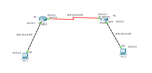
2. Configure IP addresses on the PCs and the routers.
Router 1
R1(config)#
R1(config)#int fa0/0
R1(config-if)#ip address 10.0.0.1 255.0.0.0
R1(config-if)#no shut

R1(config-if)#
R1(config-if)#int serial 0/0/0
R1(config-if)#ip add 20.0.0.1 255.0.0.0
R1(config-if)#no shut
Router 2
R2(config)#
R2(config)#int fa0/0
R2(config-if)#ip add 30.0.0.1 255.0.0.0
R2(config-if)#no shut

R2(config-if)#
R2(config-if)#int serial 0/0/0
R2(config-if)#ip add 20.0.0.2 255.0.0.0
R2(config-if)#no shut
IP configuration on PCs
Click PC->Desktop->IP Configuration. On each PC assign these addresses:
PC1: IP address: 10.0.0.2 Subnet mask 255.0.0.0 Default Gateway 10.0.0.1
PC2: IP address: 30.0.0.2 Subnet mask 255.0.0.0 Default Gateway 30.0.0.1
And now:
3. Configure RIPv2 on the routers
Router 1
R1(config)#

R1(config)#router rip
R1(config-router)#version 2
R1(config-router)#network 10.0.0.0
R1(config-router)#network 20.0.0.0
Router 2
R2(config)#

R2(config)#router rip
R2(config-router)#version 2
R2(config-router)#network 20.0.0.0
R2(config-router)#network 30.0.0.0
As you can see,to configure rip on each router,we enable enable RIP using router rip command then advertise the networks directly connected to the router interfaces using network command.
That’s all for RIP configuration.
4. We’ll now verify RIP configuration.
To verify that RIP is in deed advertising routes,we can use the show ip route command on R1.
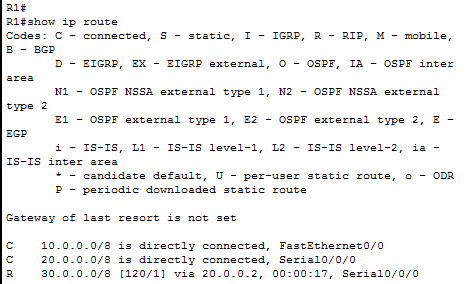
You can see that R1 has learned about the 30.0.0/8 network. The letter R indicates that the route was learned using RIP.Note the administrative distance of 120 and the metric of 1 in the [120/1] part.
To specifically display routes learnt through RIP use show ip route rip command on the router.
Now lets Ping PC2 from PC1 to further confirm that connectivity is really established between the two subnets.
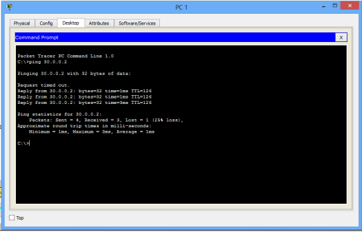
Ping test should succeed.
That’s all for this tutorial.
All the best!
You may also like to read:

thank you .
LikeLike
..
LikeLike