
Welcome to this tutorial! This is a simple step by step guide of configuring VLAN and interVLAN routing on a Cisco switch. But just before get into configurations , let’s have a brief overview of what’s a VLAN.
What is a VLAN?
A Virtual LAN (VLAN) is simply a logical LAN, just as its name suggests. VLANs have similar characteristics with those of physical LANs, only that with VLANs, you can logically group hosts even if they are physically located on separate LAN segments.
We treat each VLAN as a separate subnet or broadcast domain. For this reason, to move packets from one VLAN to another, we have to use a router or a layer 3 switch.
VLANs are configured on switches by placing some interfaces into one broadcast domain and some interfaces into another. For this tutorial, we’ll configure 2 VLANs on a switch. We’ll then proceed and configure a router to enable communication between the two VLANs.
So then,
- In Cisco Packet Tracer, create the network topology as shown below:
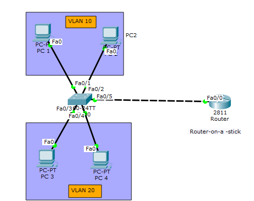
2. Create 2 VLANs on the switch: VLAN 10 and VLAN 20. You can give them custom names.
Switch#config terminal
Switch(config)#vlan 10
Switch(config-vlan)#name SALES
Switch(config-vlan)#vlan 20
Switch(config-vlan)#name IT
3. Assign switch ports to the VLANs. Remember each VLAN is viewed as separate broadcast domain.
And just before you configure, have in mind that switch ports could be either access or trunk.
- An access port is assigned to a single VLAN . These ports are configured for switch ports that connect to devices with a normal network card, for example a PC in a network.
- A trunk port on the other hand is a port that can be connected to another switch or router. This port can carry traffic of multiple VLANs.
So in our case, we’ll configure switch interfaces fa 0/1 through fa 0/4 as access ports to connect to our PCs. Here, interfaces fa 0/1 and fa 0/2 are assigned to VLAN 10 while interfaces fa 0/3 and fa 0/4 are assigned to VLAN 20.
Switch Interface fa0/5 will be configured as trunk port, as it will be used to carry traffic between the two VLANs via the router.
Switch>enable
Switch#config terminal

Switch(config)#int fa0/1
Switch(config-if)#switchport mode access
Switch(config-if)#switchport access vlan 10

Switch(config-if)#int fa0/2
Switch(config-if)#switchport mode access
Switch(config-if)#switchport access vlan 10

Switch(config-if)#int fa0/3
Switch(config-if)#switchport mode access
Switch(config-if)#switchport access vlan 20

Switch(config-if)#int fa0/4
Switch(config-if)#switchport mode access
Switch(config-if)#switchport access vlan 20
Worth noting: We could have configured all the above interfaces as access ports using interface range command as shown below:
Switch(config-if)#int range fa0/1-4
Switch(config-if-range)#switchport mode access
In the above commands, we have specified an interface range and then proceeded to configure all the ports specified as access ports.
Interface fa0/5 is configured as trunk and will be used to for inter-VLAN communication.
Switch(config)#int fa 0/5
Switch(config-if)#switchport mode trunk
The next thing is to:
4 . Assign static IP addresses to the four PCs which are located in the separate VLANs. PC1 and PC2 fall in VLAN 10 while PC3 and PC4 fall in VLAN 20.
PC1 IP address 192.168.1.10 Subnet mask 255.255.255.0 Default gateway 192.168.1.1
PC2: IP address 192.168.1.20 Subnet mask 255.255.255.0 Default gateway 192.168.1.1
PC3: IP address 192.168.2.10 Subnet mask 255.255.255.0 Default gateway 192.168.2.1
PC4: IP address 192.168.2.20 Subnet mask 255.255.255.0 Default gateway 192.168.2.1
And now it’s very clear that we treat a VLAN just like a physical LAN when assigning IP addresses.
At this point let’s try to test connectivity within VLANs and between VLANs
To test communication between hosts in the same VLAN:
Ping PC2 from PC1 both in VLAN 10. Ping test should be successful.
To test connectivity between hosts in different VLANs:
Ping PC3 in VLAN 20 from PC1 in VLAN 10. Ping here will definitely fail. Why? Because inter-VLAN routing is not yet enabled. Hope you can see how we’ve used VLANs to place the hosts into two logical networks which can be viewed as separate broadcast domains.
Now, in order to allow the hosts in the two VLANs to communicate, we need to do something extra. And you can guess what. We’ll configure the router to permit inter-VLAN communication. Let’s do that right away.
5. Configure inter-VLAN routing on the router
We’ll configure the router so that it will enable communication between the two vlans via a single physical interface. How is this made possible? We’ll divide the single physical interface on the router into logical interfaces (sub interfaces). Each sub-interface will then serve as a default gateway for each of the VLANs. This scenario is called router on a stick (R.O.A.S) and will allow the VLANs to communicate through the single physical interface.
Wort noting: We can’t assign an IP address to the router’s physical interface that we have subdivided into logical sub-interfaces. We’ll instead assign IP addresses to the sub interfaces.
So let’s do router configurations:
Router>enable
Router#config terminal

Router(config)#int fa0/0
Router(config-if)#no shutdown

Router(config-if)#int fa0/0.10
Router(config-subif)#encapsulation dot1q 10
Router(config-subif)#ip add 192.168.1.1 255.255.255.0
Router(config-subif)#

Router(config-subif)#int fa0/0.20
Router(config-subif)#encapsulation dot1q 20
Router(config-subif)#ip add 192.168.2.1 255.255.255.0
As you can notice from above, the routers physical interface fa0/0 was subdivided into two sub-interfaces( fa0/0.10 and fa0/0.20) , which are then configured as trunk interfaces and given IP addresses.
Finally,
6. Test inter-VLAN connectivity.
Here we’ll test connectivity between computers in different VLANs . Don’t forget that its the router that enables inter-VLAN routing.
Ping PC3 in VLAN 20 from PC1 in VLAN 10. If everything is well configured, then ping should work perfectly.
And that’s all!
Hope this article was useful to you. Comment to help improve it.
All the best.
See also:

Nice Working setup…
LikeLike
Hey there, I think your blog might be having browser compatibility issues. When I look at your blog in Ie, it looks fine but when opening in Internet Explorer, it has some overlapping. I just wanted to give you a quick heads up! Other then that, excellent blog!
LikeLike
why would you be using internet explorer, sounds like you are the problem
LikeLike
Uncalled for, Rude
LikeLike
LOL
LikeLiked by 1 person
honestly tho you so real for that
LikeLike
Followed instructions to the letter, didn’t work.
LikeLike
hello
this artical wasn PC1 from vlan 10 and PC4 in vlan 20 really helpful to me
but in my case i can only ping between PC1 from vlan 10 and PC4 in vlan 20
can’t ping between PC3 and PC2.what could be the problem ?
LikeLike
Vlan meaning is that one host from one vlan shouldn’t see hosts from another vlan.
LikeLike
This is a very nice one and gives in-depth information. I am really happy with the quality and presentation of the article. I’d really like to appreciate the efforts you get with writing this post. Thanks for sharing.
ccie security training in pune
ccie R&S training in pune
LikeLike
this is verry simple configuretion thanks for your help
LikeLike
This site was… how do you say it? Relevant!!
Finally I’ve found something that helped me. Thanks a lot!
LikeLike
Thanks for finally writing about > How to configure VLAN and interVLAN Routing
in Packet Tracer – Computer Networking Tips < Loved it!
LikeLike
Very useful. Thanks
LikeLike
This is informative and its helpful… yoy have put it clear and simplified. Thanks
LikeLike
Inter-vlan not working…
LikeLike
very thanks,
LikeLike
not working
LikeLike
Thanks very much for teaching me VLANs
LikeLike
i try the all instruction but i cannot ping pc1 vlan 10 to pc3 vlan 20
LikeLike
thanks
LikeLike
bot ala betchy
LikeLike
Its very clear,it’s understandable thank you so much
LikeLike
Thank you very much I have been finding it difficult to understand this configuration of vlan for long, but you have made it very easy for me.
LikeLike
Yeah…didn’t work. Sounded cool, though. Thanks anyway.
LikeLike
TU PUTA MADRE NO FUNCIONA
LikeLike
soy muy sensual y traviesa con mis click here tacones y todo, mi cuerpo
LikeLike
great work well done it was awesome
LikeLike
tang ina mo po
LikeLike